Happy International Amateur Radio Day ! 73 DE YO6DXE
QRP Multi-Z Antenna Tuner Experiment
If you enjoy the video be sure to SUBSCRIBE »
Get $5 of New User Free Credit using PCBWay. Full feature custom PCB prototype services, PCB assembly, SMD stencils and CNC / 3D Printing.
A simple QRP multi-z antenna tuner. Easy to tune low-z and high-z antennas. Still not sure about how well it performs. Hopefully it will do ok for 80m, 40m and 20m band. I just got a nanoVNA so I will experiment with the number of turns on the inductor and the values of the capacitor. I thought is a nice project to experiment with, so it was worth building it.
At the end I also decided to ad a resistive bridge LED SWR meter. This helps me tune the antenna a lot easier with ought an external SWR meter. It is a work in progress, so the information I have here is not that accurate yet. You may want to experiment with the number of turns and the taps.
BASIC PRINCIPLES OF THE HOMEBREW ATU
There are two types of antenna tuners depending on the impedance of your antenna. The series circuit and the parallel circuit, both shown in the images down bellow. I wanted to build something that would allow me to switch between series and parallel. This way I would end up with a multi-z antenna tuner. Because I wanted to also see how well I adjust the SWR, I also incorporated the resistive bridge LED SWR meter. This helps me tune the antenna the best I can. It is the first one I built, so I’m still experimenting with it.
I actually watched a video of Charlie Morris ( ZL2CTM ) building a homebrew ATU and that is how I decided to also try one. The ideal multi-z antenna tuner would allow you to tune nearly every piece of wire to an acceptable SWR. Let’s see how this will turn out at the end and if it’s worth building one.
MULTI-Z ANTENNA TUNER SCHEMATIC
This is not a schematic I came up by any means. I just combined a lot of the information that I found online. I tried to keep it as simple as possible, using the parts I had at hand. I’m sure that with a little effort, this can be improved a lot more. At the time I built this homebrew ATU I had nothing to measure the performance with.
Recently I got a nanoVNA, so this is the schematic with the latest modifications. The only improvement I will do in the future, is to place a switch for the inductor with 12 steps instead of 7 as I have now. What I can tell from the start is that this ATU is good and helps me tune on nearly all HF bands. I only used 20m of wire for the antenna and a 4m wire as counterpoise… but the ATU as it is now has limitations that’s for sure.
THE INDUCTOR AND THE CAPACITOR
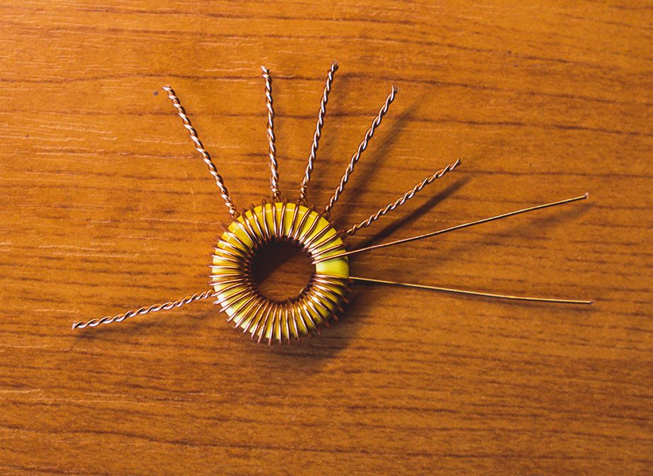
The heart of the circuit are the inductor and the variable capacitor. I decided to go with a toroid version using a T68-6 toroid. Because I only had a seven positions switch, the number of taps I could make was limited. I think a twelve positions switch would be a lot better. Also the variable capacitor I had was from 10pF to 230pF. If I would have one with a bigger value would be better. I think 300pF or 500pF would be way better. But I used what I had on hand. I removed the switchable extra 220pF capacitor in parallel with the variable one.
The number of turns on the inductor were limited by the thickness of the wire I used. You will notice that in the video I have the taps differently comparing to the schematic I have here. This is because I am still experimenting with the antenna tuner. I will do more tests and experiments, then I will put the final details when I’m happy with the results. So far is still in the developing process. Feel free to experiment as much as you want.
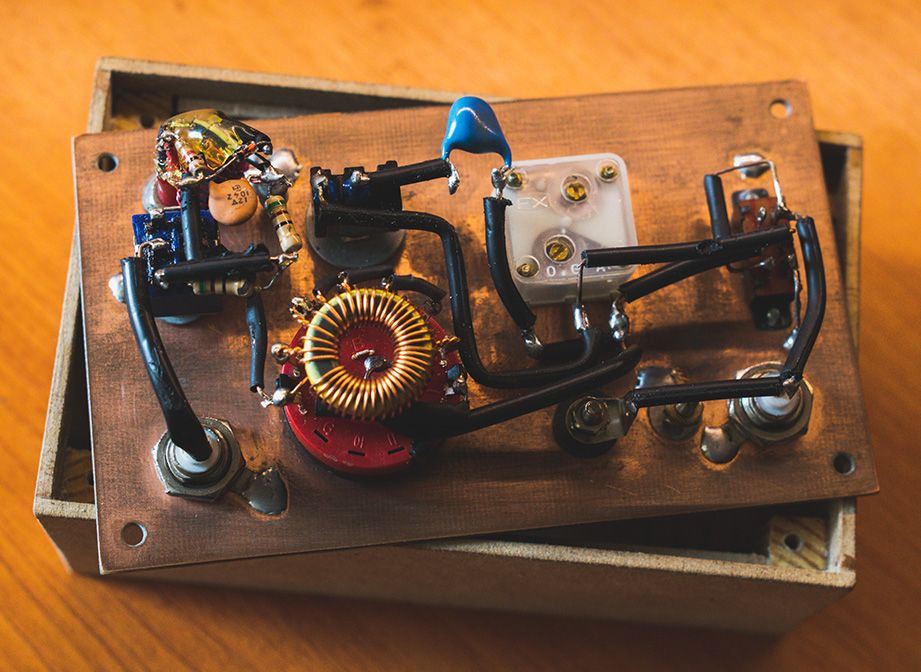
In the images on top you can see the way I built the inductor using the T68-6 toroid. Also you can see the finished built of the homebrew ATU. Clearly not of my most beautiful pieces of work, but it does the job. Initially I wanted to build it on a nice and properly made PCB board, just like the commercial ones.
I just wanted to experiment with it, as I know that in general there is a lot of signal loss when using ATU’s, so I don’t plan on using it very often. But I guess it’s good to have one, as I never know when I may need it. When building it, make sure you keep all the wiring as short as possible… not as I built mine ( ha ).
ATU vs 49:1 IMPEDANCE TRANSFORMER
I was curious if for portable work I should use the 49:1 impedance transformer, or an ATU ? Here you have a quick comparison using the same 20m of wire antenna, as a half wave 40m band antenna. Turns out in my opinion that an ATU may be more reliable helping me get more bands out of the same antenna. On the other side, the 49:1 impedance transformer is smaller in size and it does not need constant adjustments when changing bands.
ATU PERFORMANCE
Before receiving my nanoVNA, the only tests I could make were using the built in LED SWR meter. I tried tuning random wires with or with ought a counterpoise. These days I tested it a little more and down bellow you also have the comparison test video I made, between the ATU and the 49:1 impedance transformer.
Once this ATU will perform as I wish it should be and I am happy about it, I will try to think of a PCB design that will help you build it really quick and compact with not many wires all over the place. As I was saying, I just wanted to experiment with and see how it performs. But well built it has chances to be really useful.
So far I can say that having both High Z and Low Z in one tuner with limited capacity and inductance is not that great. That is because it doesn’t seem to perform well in both cases. If I adjust it to work well for High Z, it won’t work well on Low Z… and the other way around. It was nice to experiment with, but to be honest I think I will just keep the High Z part for portable work. For Low Z at home I will build another ATU.
73 DE YO6DXE
Check the latest EXCLUSIVE DISCOUNTS offered to the DX Explorer blog readers. Discount codes for various products and services offered by partners and collaborators.


bonjour merci pour cette article sur les boites accord ca va m’aider pour construire les mienne merci en encore 73 51 a vous
Toujours un plaisir Olivier. Ce n’étaient que des tests pour voir ce qui pourrait mieux fonctionner. J’espère qu’en décembre j’aurai le temps de construire une version finale à avoir sur le bureau. J’essaie d’utiliser des antennes mieux réglées et de ne pas trop utiliser le tuner d’antenne, mais il est préférable d’en avoir un juste au cas où (ha).
73 YO6DXE
Да да схему повторил работает правда последовательным включении кондесатора.
Да, это работает в обе стороны. Это зависит от импеданса антенны.
73, YO6DXE
Приветствую вас! Коллега, попробовал по вашей схеме работает! (Живу в Забайкальском крае. подобные простые устройства помогают в радиолюбительстве , благодарю вас..!)
Привет, Валерий… Я рад слышать, что это работает. Если у вас больше емкости и переключатель с большим количеством положений, чтобы иметь больше значений индуктивности … еще лучше. Я тоже люблю простые схемы. Я не очень увлекаюсь всеми этими новыми цифровыми технологиями. Привет из Трансильвании, мой друг. P.S. Извините за поздний ответ… Меня немного не было дома.
73, YO6DXE